Arduino MIDI Clock Tutorial for Beginners
Arduino, as we know is capable of carrying out complex tasks than a simple microcontroller. Sometimes, you may want to synchronize a self-made sequencing circuit to MIDI Clock Signals. In Order to do so, you need to get a hold of MIDI communication and Arduino is one of the best ways to do so.
First of all, you must be aware of the difference between a byte and a bit. While both are units for storage, a byte is a packet of data made up of 8 bits. A MIDI protocol, like many others, use the 8-bit byte convention. A bit may store a 0 or 1, e.g. 11010111
The left most bit is called the most significant bit or MSB while the right most bit is called the least significant bit. A binary number can be converted into a decimal number using a variety of converters; you don’t need to grind yourself with this:
While you can write application specific code to deal with MIDI clock signals, a skeleton code will do the trick and clear your concepts, helping you to synchronize several MIDI hardware like Ableton Live, Pro Tools, etc. to a MIDI clock.
A MIDI beat clock or clock is a signal that is sent through the MIDI protocol to make sure that the plethora of MIDI powered devices stay in sync. MIDI messages usually comprise of 2 – 3 bytes but unlike these messages, MIDI clock messages are only a byte in length.
The following are the major MIDI clock bytes in use:
 start = 0xfa
 stop = 0xfc
 clock tick = 0xf8
 continue = 0xfb
When the host sequencer is running, a total of 24 clock tick bytes are sent per quarter note. When the sequencer comes to a halt or pause, the stop byte is sent, while when the sequencer starts after getting stopped, the start byte is sent again. In the case where the sequencer is paused and then started, the continue byte is sent.
Code
For every clock tick, “something” can be done, using the information devised above. All you need to know is what to do after every clock tick, and then add the functionality to the code below:
byte midi_start = 0xfa;
byte midi_stop = 0xfc;
byte midi_clock = 0xf8;
byte midi_continue = 0xfb;
int play_flag = 0;
byte data;

void setup() {
 Serial.begin(31250);
}

void loop() {
 if(Serial.available() > 0) {
 data = Serial.read();
 if(data == midi_start) {
 play_flag = 1;
 } else if(data == midi_continue) {
 play_flag = 1;
 } else if(data == midi_stop) {
 play_flag = 0;
 } else if((data == midi_clock) && (play_flag == 1)) {
 Sync();
 }
 }
}

void Sync() {
 // do something for every MIDI Clock pulse when the sequencer is running
}
Diagram
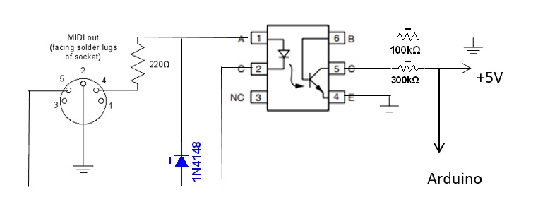
The IC used is 4N28, optocoupler. You may employ the help of the datasheet for modifying the existing design.
Conclusion
All you need to do now is fill in the “Sync” block, and you’ll be good to go.
Leave a Comment
3 comments
Connecting the Arduino RX input to 5volt will not work. The Arduino RX input should be connected directly to pin 5 of the 4N 28 and the resistor of 300k is used as pull-up sot that connects to 5volt.
Midi inputs (as in your diagram) should not have the earth connected to pin 2. The earth is only connected on a midi output connector. The idea of having an opto-isolator is to break any earth loops, and if you connect the earth at both ends, you remake the earth loop – bad idea.
Good tip!